TILE - The building instructions
- Björn Kempf
- Jul 4, 2024
- 5 min read


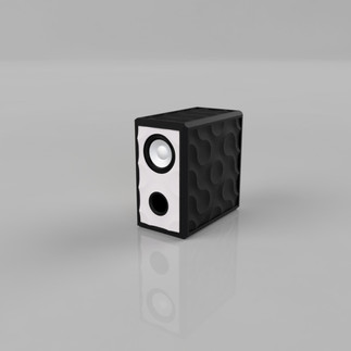
TILE - English for "tile" is pronounced "part". This case got its name from its outer skin. This consists of printed tiles and gives the case its special appearance.
What do we need for assembly and manufacturing? :
The Base 3.AL loudspeaker kit from Blue Planet Acoustic
Approximately 1250g of material per housing, of which 750g are needed for the tiles
6 Allen screws M4x20mm with matching nuts
2 pairs of gold contact plugs with M5 thread
soldering iron
Allen key
adhesive
20 spring clips
3D printer
The spring clips

Spring clamps are used for later assembly. The clamps shown here are available in packs of 20 at a good price. The shape of the clamps is also ideal for holding the connection securely. You can get them here .
The adhesive

For bonding, I recommend Pattex Crocodile . This adhesive is the ideal partner for secure and sealing bonding of PLA parts.
2 tubes are more than enough for mounting 2 housings.
The printer, if you don’t already have one

The printer for this project should have a usable printing area of 220mm x 220mm. I have an Anycubic Kobra 2 pro because it has some advantages compared to its counterparts of the same size and design. There will be a video about this.
Preliminary considerations
There are some design options that I would like to show you briefly in the following gallery. Maybe you like some of them and would like to recreate them:


Now it starts
We need to make the first parts. The parts or the part I am talking about are shown in red in the picture.
In the first step, we produce all parts that have a thread. These parts are printed with different settings than the rest.
Threaded sleeve and screw

Both the threaded sleeve and the screw should be printed with a layer thickness of 0.1 mm. The threaded sleeve is printed without infill because it is a very thin-walled part.

The screw is aligned with the thread facing downwards on the print bed. With a 0.4mm nozzle, 2 wall lines and 15% infill are completely sufficient. You can decide the number of lower and upper layers yourself, I would recommend 2-3 layers.
In my first attempt to print the threaded sleeve, the part came loose. To counteract this, cleaning with detergent and warm water and using a 3D varnish as an adhesive helps.
Alternatively, you can use a brim to increase the contact surface or reduce the printing speed.
Frame baffle

For the baffle, the layer height is increased again to 0.2mm. I print this part with 2 wall lines and 20% infill.
You should set 3 upper and lower layers to achieve the necessary stability later. You should place the seam of the front on one of the lower edges so that it is not visible later.
Assembling the front

The 3 parts of the front are then assembled according to this illustration.

The threaded sleeve is glued to the baffle at the marked points.
Allow the adhesive to dry for at least 2 hours

For later assembly we still need the cover ring. We can print this with the previously selected settings for the baffle.
However, it is only needed at the end of the assembly.
More pieces
The other frames will then be printed using the settings for the front. You will need:
2 x side wall
2 x frame cover and back panel
1 x floor
1 x lid for base
Preparing the soil

Before gluing the shells of the housing together, you should insert the nuts on the inside of the base. To do this, simply use a screw to push the nut flush into the base.
Assembling the housing parts
To ensure that this step is successful, you should follow the following steps carefully.

The orange clamping jaws should be removed before use. They will only be a hindrance later
Another note about the glue:
If any glue gets on surfaces that will be visible later during the following steps, just let it dry. Once it has dried, it will be much easier to remove.

With the help of the spring clips the complete housing is now assembled, without glue!
In this state, the individual parts are aligned until everything fits together.

We now lay the case on its side and remove all the clips that hold the side panel.
The adhesive is now applied to the connecting surfaces of the front and rear walls.
No adhesive is applied to the lid and base!
The side panel is then reinserted and secured with the spring clips.
The second side wall is then glued in the same order and on the same surfaces.

Now we turn the case upside down and remove all the clips that hold the bottom.
The adhesive is now applied to all 4 adhesive surfaces. The base is then put back in place and secured with the spring clips.
We repeat this process with the lid of the housing.
After that it should look like this again, but now all 12 surfaces are glued together.
The case should now dry for 12 hours.
The tiles

For now, I've decided on this design in my example. I say "for now" because I want to see how the black harmonizes with the gold.

The back wall is a good introduction to the world of tiles. If the setup for the printer isn't right yet, it might not be so bad.
For the back wall you need:
6 x tile
2 x Tile Terminal
Before gluing the tiles into the back wall, I would try a "dry run" to make sure that everything fits. The holes in the back wall can be used to get the tiles out of the back wall again.

A ring made of adhesive is applied to the area of the holes to seal them.

The tiles can then be inserted. I chose a slightly different pattern. When arranging the tile for the terminal, make sure that it also sits on the bottom of the housing.
The tiles for the top and side walls can now be printed.
For the lid you need:
8 x tile
For the side walls:
16 x tiles each


This is what the interim result looks like. Now the front is missing.
The following tiles are required for the front:
4 x Tile V2 baffle
4 x Tile V2 BR
The tiles on the front require a little more feeling to install than the tiles on the other sides. Be patient and take the time you need. Start with the tiles in which the bass reflex tube will later be located.

Now that the front is glued, you should give the case some time (2 hours) to dry. The case will only be strong enough after 12 hours. Then the glue will be completely hardened.

Then the cover ring comes into use. The adhesive film should be as thin as possible.

To assemble, you can place the case on the front and insert the ring.
Alternatively, you can also use the brackets.
On some materials the clamps will leave scratches in the surface, like in my case on the black parts. Give the case 12 hours to dry.

Then screw the chassis into the housing with the nut. You should solder the cables beforehand.

The adhesive for the bass reflex tube is applied to the tube behind the collar. After it has been inserted, you should wait an hour for the adhesive to dry. Then you can continue.

The Bondum is now laid out on the edge. Behind the bass reflex tube there is a piece of insulation wool in which the blocking circuit is also rolled. The parts are very light and do not need to be screwed together.
The terminals should also be connected.

Now the floor gets another layer of insulating wool. Then the lid can be screwed on.


Have fun recreating it.
Björn Kempf


Comments