
Solo 15 and Little Eli - how is it done?
- Björn Kempf
- Feb 18, 2024
- 9 min read


The Solo15 from Visaton is a very popular kit in the scene. I really like the 4 inch tiny, which is why it is a good choice for the Little Eli case.
In this article I would like to describe the necessary preliminary considerations and the individual steps in more detail so that you can easily make them yourself.
The production of the case actually takes place parallel to the creation of this report, as you can see from the time stamp of the respective section.
Grab some chips, it'll take time.
Have fun
Another piece of information on our own behalf. This post may contain affiliate links to other websites. If you follow these links and make a purchase on these sites, I will receive a small commission. The products don't cost you a cent more, but you support my projects. Thank you for that.
I deliberately do not go into manufacturing times in the report. If you recreate this project, you will most likely do so with a different printer and material.
February 10, 2024 11:00 a.m
The first preliminary considerations
The printer
In order to print and assemble the Little Eli, you need a 3D printer. This should have a print bed measuring 220mm x 220mm and be able to print bodies up to a height of 220mm.
The largest body to be printed measures 175mm x 218mm and is 218mm high. This should fit most common devices.
On 3DJake you will find a large selection of the latest devices.

The material
There is the motto "Shit in - shit out". Work with materials from a good manufacturer and don't buy junk. In total, you need around 3.5 kg of filament to make one housing. PLA is best suited for production. This is a very hard plastic that is also available in an endless variety of colors.
Tools and others
Tool
The tools required are quite manageable:
3mm Allen key
7mm open-end wrench
Soldering iron and solder
Scissors
Sandpaper (240 euros)
Cutter knife
Adhesives
Hard plastic glue
Superglue
materials
Convoluted foam
Insulating wool
Foam cord
Miscellaneous
Some nuts and bolts
Washers
Kit
SOLO15 kit
The print data
Preparation
The print data is contained in a ZIP file. You have to unpack that first. In it you will find all the necessary bodies that you should create. For clarity, all parts begin as follows:
LS - Parts that belong to the housing in which the chassis is located
VR - Parts that belong to the housing in which the channel is located
BR - Parts that belong to the housing in which the bass reflex tube sits
The order in which you make the parts is up to you. I've gotten into the habit of printing parts that run for several hours overnight.
Preliminary considerations
The standard in 3D printing is to use a 0.4mm nozzle. However, the housing can be manufactured much more quickly with a 0.6mm nozzle. However, with both options you get approximately the same result. I prefer to use 0.6's.
Slicer settings
My recommendation:
Soil layers | Wall lines | Cover layers | Infill | |
|---|---|---|---|---|
0.4mm nozzle | 4 | 3 | 4 | 20% |
0.6mm nozzle | 3 | 2 | 3 | 15% |
To the bodies
I would want to divide the bodies to be printed into 3 categories.
Visible housing parts - So that the parts land on the plate quickly, you can work with higher layers here. With a 0.4mm nozzle this works very well up to 0.25mm. With the 0.6mm nozzle, 0.3mm can be achieved. Try this out first on a part that you won't see later.
Threaded parts - You should always print threaded parts with a layer height of 0.2mm, regardless of the nozzle used.
Parts with support structures - Only the back covers, and actually only these parts, require the so-called support.
Let's go
Print the first parts
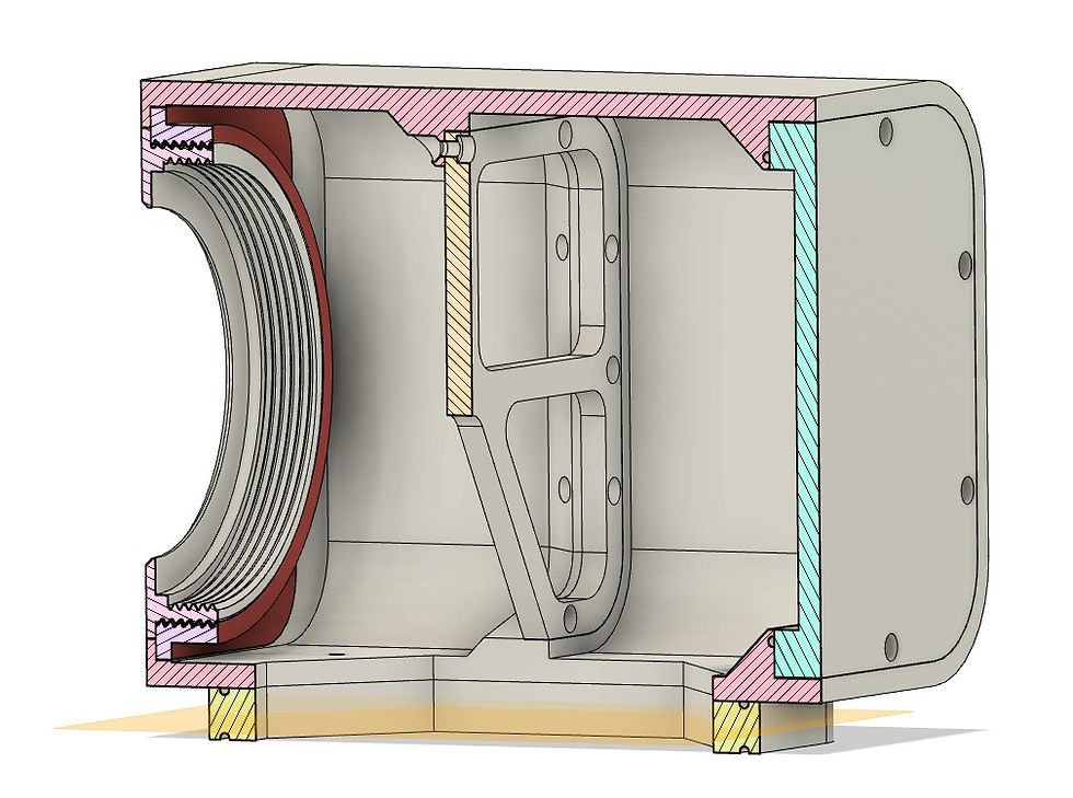
I'll start with the parts of the LS case, with the part shown here in red. Since this part has a thread, I select a layer height of 0.2mm as described above.

The material requirement is approx. 70g
Don't forget to set the layer thickness setting to 0.2mm.
February 10, 2024 1:00 p.m

The part is finished. I ran out of black material and used the rest of another coil. You can do that with this part because you won't see it later anyway.

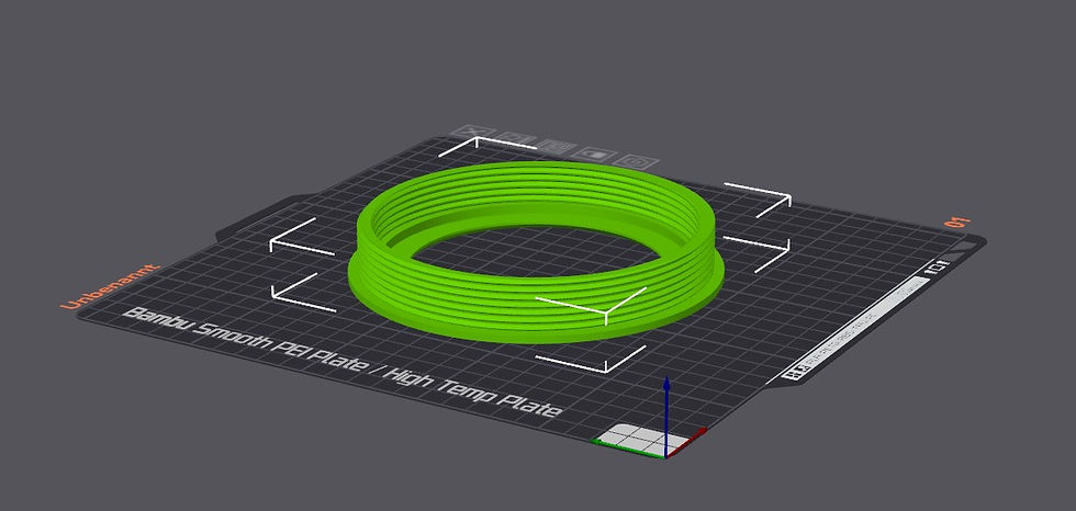
Since I've just clamped the green filament anyway, I'll use it to print the screw.

For the screw you need approx. 34g of filament. Here too, the layer height is set to 0.2mm again.

That was really the rest of the green material. The last 50cm ended up in the bin.
February 10, 2024 3:00 p.m

Then comes the turn of the inner strut. I clamped black again because the following part will also be black.

On this part, make sure that the countersinks for the screws face upwards. Then you can make this part without any support structures.
50g of material is required.

Looks good. If you want, you can print this part again. It is also used in the BR housing.
The stiffening in the VR housing looks different!

We continue with the connector.

Here too, 80g of material is required.
February 10, 2024 6:00 p.m
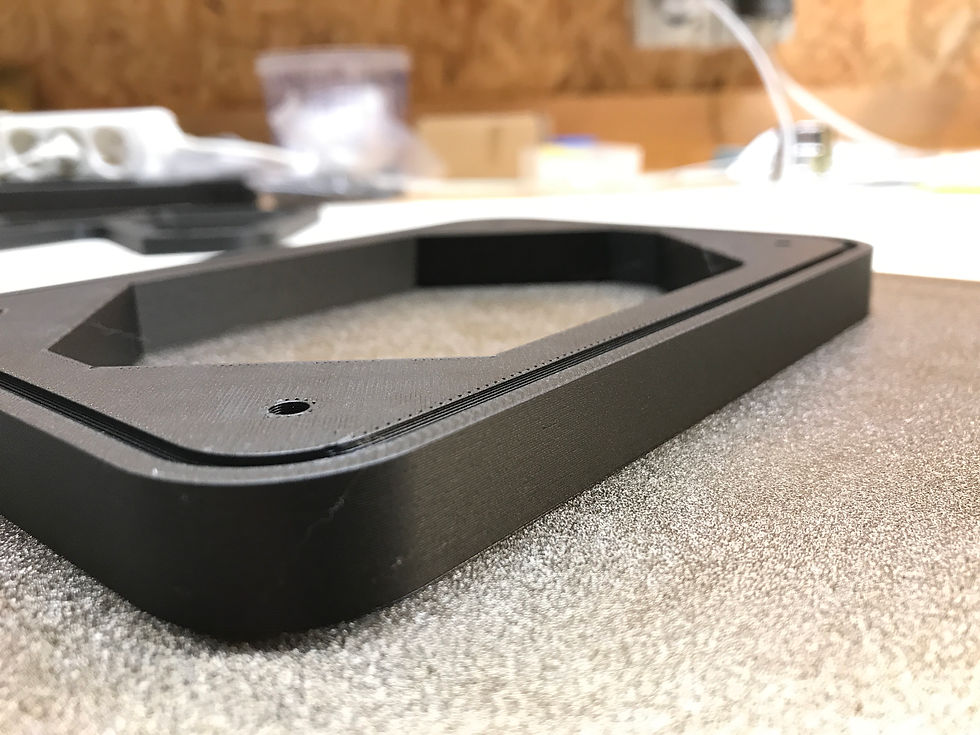
We now have 2 pictures of the connector here. Here it is exactly the same as with the struts. You can print a second one straight away.
You can take a look at the printed image in the close-up. A 0.3mm layer height can look so beautiful.
I think it makes the pieces look a little more authentic.
That would be my haul for today. The second brace no longer fits into my schedule. I'll print them tomorrow when we screw the first screws into the housing part.
February 10, 2024 8:00 p.m

As described above, I save the cross-country skiers for the night. I can still see the start of printing and the first 2-3 hours. If what I see is promising, I'll let it continue
For this part you need approx. 750g of material.

For the first part of the case I have to get rid of a few clocks that should be taken into account.
Depending on the printing surface, you should work with a brim. The brim (blue in the picture) increases the contact surface of the part and prevents high corners or the part from coming loose
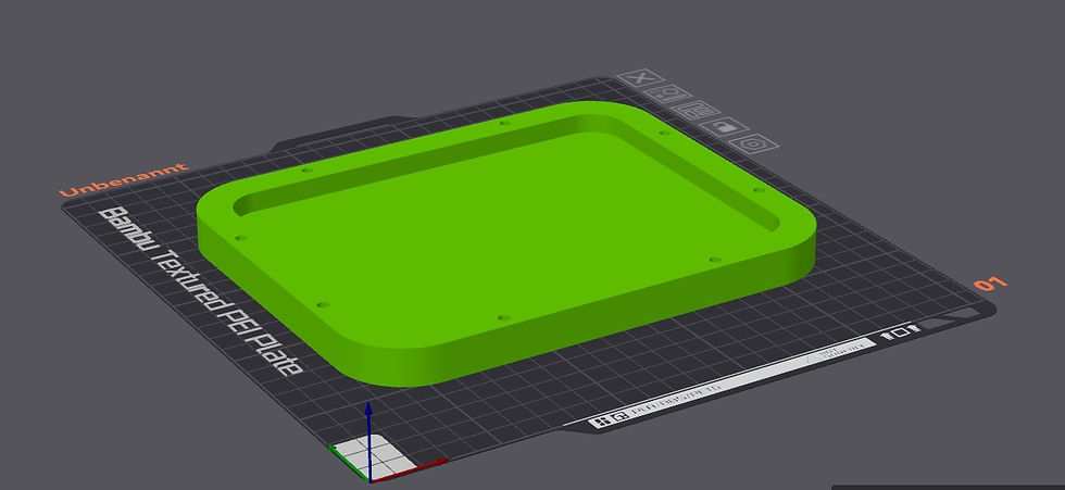
We print the upper part of the speaker housing. You should place the seam (white in the picture) in a place where you won't see it later.
This part is also printed without supports. Even the depressions pointing downwards do not need any supports!
For these larger pieces, pay attention to an optimal first layer. It is crucial for all subsequent layers.
February 11, 2024 10:30 a.m

The upper part of the case is finished. Give the piece a little time to cool when it's finished.
At this point you should check whether the previously jerked parts also fit. I design with relatively little scope. If something is stuck, you can refinish the parts with some sandpaper.
In this part we can also pull the nuts into the countersinks. By the way, these are deliberately not hexagonal. The mother should just be immersed in the depression.

The screws then remain screwed in. We only turn them out when we need them.
Normal nuts are used!

We continue with the lid.
In order for the lid to be successful, supports must be used. These ensure that we have a clean contact surface for the screws later.
In the picture below we see the supports shown in green.

You need approx. 150g for this part. Please do not print this part twice. The cover of the BR compartment has 2 additional holes for the connection terminal.

The lid is ready. You should try it straight away to see if it fits into the intended opening.
If not, you would have to rework the edges a bit. Rework is only necessary if something is not calibrated correctly on your printer.

You can push out the plugs from the support from the inside with a screwdriver or Allen key. Please don't hurt yourself.
February 11, 2024 6:30 p.m

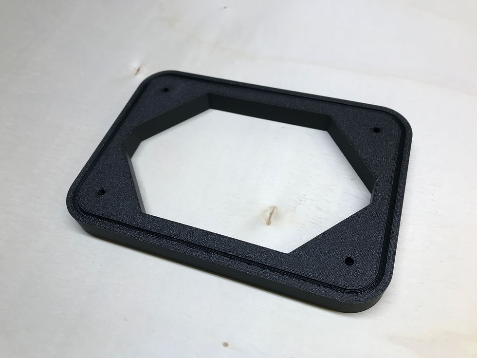
It continues with the aperture.
Don’t forget to check the layer height. Set it back to 0.2mm as there are threads on the part. 70g of material is required.

The aperture is finished. There are things to check.
Does the chassis fit in?
Are the diameters suitable for installation in the housing?
Do both threads fit?

It should then look like this. Congratulations. You have successfully mastered the first part!
February 11, 2024 6:30 p.m
It continues here tomorrow. I will print the middle housing part overnight. It should be ready sometime tomorrow. I'll then go into the specifics.
February 12, 2024 7:00 p.m

So, there it is. As with the top case, you need to choose a side where the seam will be visible. In my case I have put them on the bottom. You won't see them there unless you look at the speaker from below.

I have already finished the last part of the case.

We now take care of bracing the middle part. It is printed exactly the same as the other two struts. The orientation on the print bed does not matter because these struts have no holes. They will be glued later.

And then it's the turn of the first part of the channel and...
(170g material)
The nuts for the lid can also be tightened.

.... the inner part of the bass reflex department. Here again, the layer height of 0.2mm must be taken into account.
(80g material)
In the previously printed housing you can already insert the nuts like in the upper part of the housing. Likewise the screws for the lid.

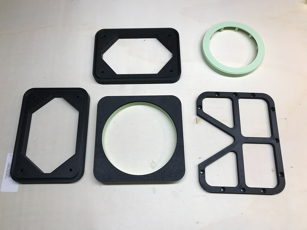
The seals can be inserted into the intermediate pieces. The length of the seal is approx. 525mm. However, it's easier to trim it if it's already pickled.

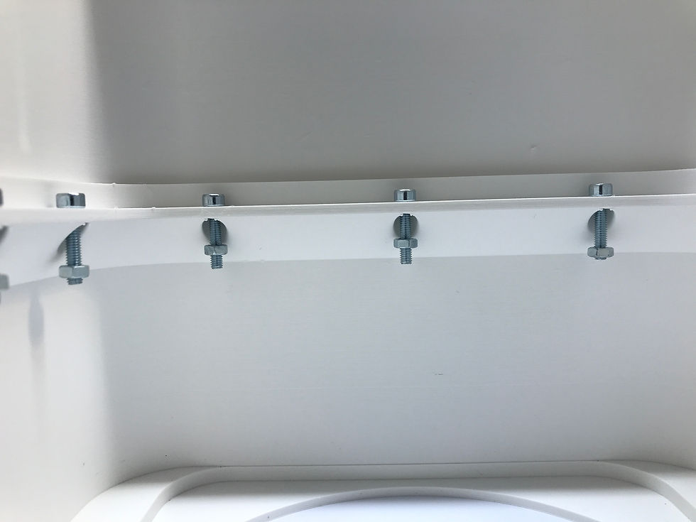
Then we can screw the 3 housing parts together. The lock nuts are used for this purpose, as well as a washer under each screw and nut.

The screws should be tightened so much that there is no gap left between the connector and the housing.
Don't slam the screws too tight!

This is what the result should look like.
02/13/2024 8:00 p.m

You should already insert the nuts into the previously moved channel.

There are no special features to consider with the bass reflex tube.
All other parts are printed according to the same scheme. I won't go into that in detail now. If you have any questions about this, just write to me.
The assembly
A bit of information in advance. We are now working with adhesives in some places. Please always follow the manufacturer's safety instructions. In some cases, the adhesives can be very dangerous to your health.

We start by completing the fronts. The middle part has some special features. We start by applying glue to the back of the case. So that we can continue working quickly, we also apply superglue at certain points. This creates the first connection and the part stays in place.

Then the first part of the channel is inserted. Just imagine the part I have in my hand. We won't need that until later.

Gluing is now carried out on the contact surfaces within the housing and on the channel. The stiffener is then put on. Please do not use superglue!

Then the spring is inserted into the channel. This ensures precise positioning and prevents adhesive from running into the channel.

The channel is then inserted into the housing.

So that everything fits together, we now tighten the outer screws on the cover screws. Unfortunately I couldn't do that because I printed out the wrong cover from an older version. :-(

The bass reflex tube and the ring for the chassis can now also be screwed in. We glue the cover for the channel in place with a little superglue.

I have now soldered the cables to the B100. I'm always a little more generous and have 1m on it. The driver will then be secured with the nut in the front.

The stiffener is then screwed together. Insulating wool is only loosely inserted above the stiffener, towards the cover. Before the lid is screwed on, a layer of convoluted foam is placed directly behind the lid.

In the middle part the two seals are inserted in the housing and the channel. The lid can then be closed. In the past I had had rather bad experiences with insulation in this area.

In the bass reflex department I used glue instead of screws. The screw connection brings no added value here.

In the variant with a switch (sorry, a bit full of crumbs from grinding) the terminal is now attached to the lid. This in turn is used to connect the switch between the chassis and the terminal.

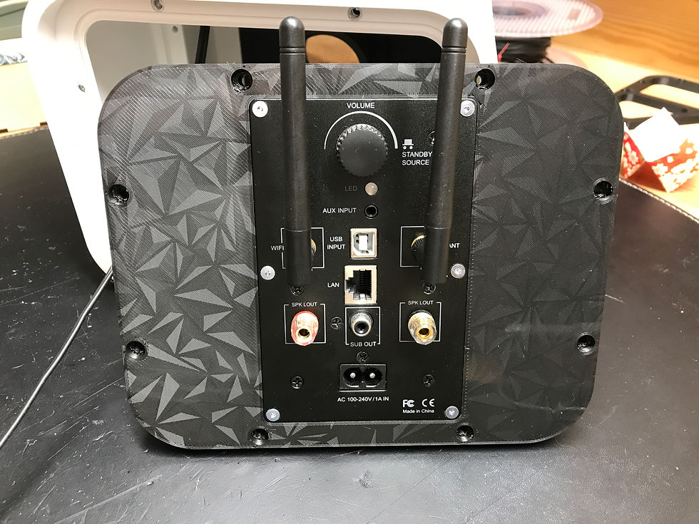
The switch is not required for the variant with an active module. This is immediately connected to the chassis.
The BR housing can then also be closed.
What can I say ? We have reached the end. In front of you is now the Little Eli in the Solo 15 variant or the active sister. In this version, the second speaker is simply connected to the active module. If you want to save yourself the cable between the two speakers at this point, you can also install a module in the other speaker. This can then be switched on as a second channel via the Arylic app.

You don't need a lot of space or tools. However, the most important tool in 3D printing is patience. If the first parts don't work right away, you look for a solution piece by piece.
I hope you had some fun with this report.
Best regards
Björn Kempf


